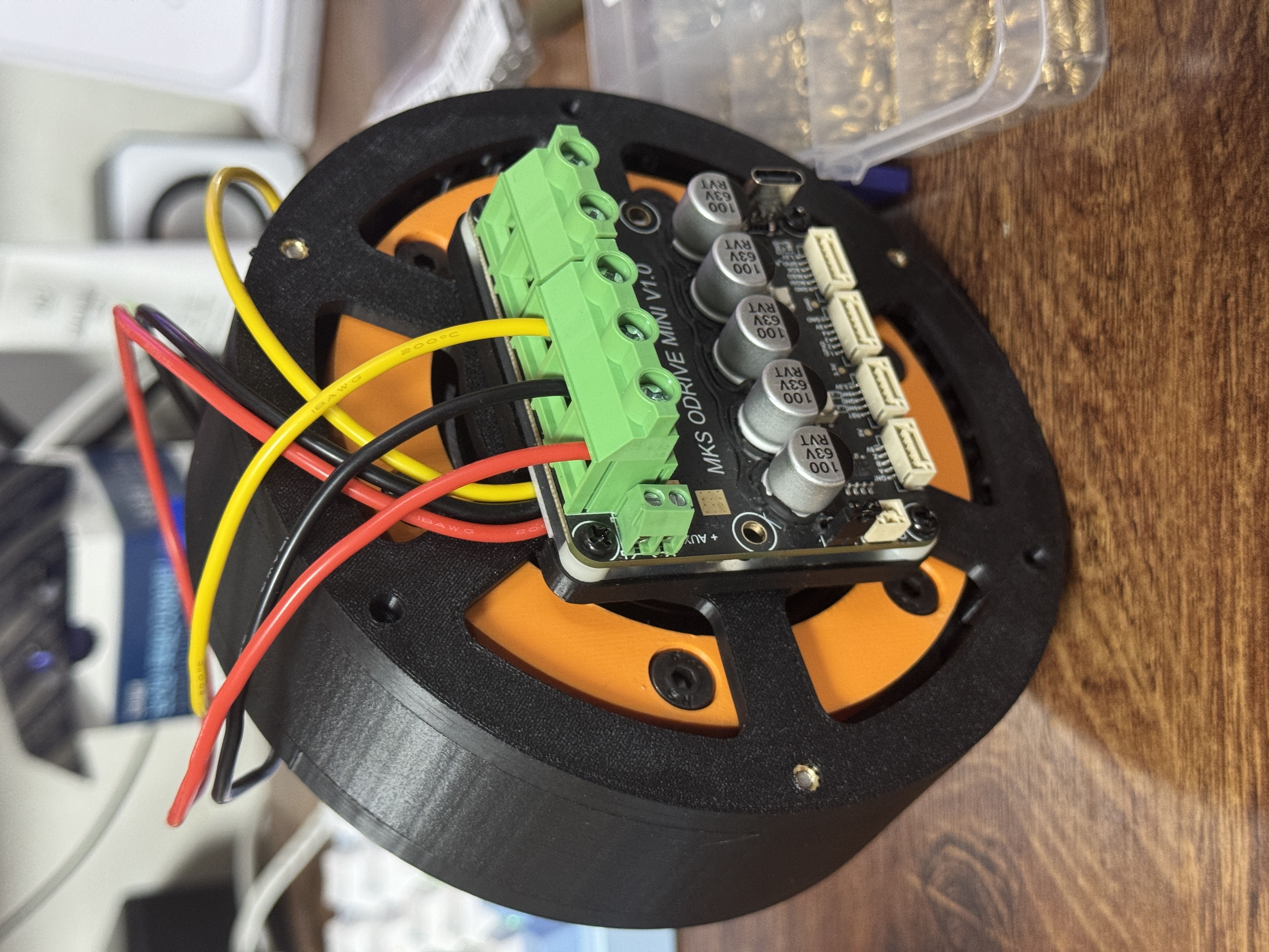
Inverse-QDD Actuator
1. Motivation
The original goal of this project was to build an actuator using a 5010 360KV motor with a 36:1 reduction ratio. My first idea was to use a planetary gearbox. However, because the achievable reduction ratio of a planetary gearbox is heavily constrained by the tooth counts of the sun gear and ring gear, it was difficult to obtain such a high ratio while keeping the actuator compact. To achieve the target reduction ratio, I initially planned to stack two 6:1 planetary gear stages on top of the motor. Although this approach worked in theory, it made the actuator much thicker than I wanted. This led me to consider placing the gearbox around the motor instead of above it.
2. Design Process
Conventional QDD actuators typically use a low-KV motor with a low-ratio planetary gearbox located inside the rotor. Since low-KV motors are relatively expensive, I wanted to see whether a similar torque could be achieved using a much cheaper 5010 360KV motor. I also explored the idea of using the motor itself as the sun gear of a planetary gearbox. Unfortunately, the resulting sun gear became too large, making it impossible to reach the desired reduction ratio.
3. Why a Cycloidal Reducer?
At that point, I realized that a cycloidal reducer was a much better solution. Unlike a planetary gearbox, the reduction ratio of a cycloidal reducer is not limited by the size of the input shaft. As long as the number of ring pins differs from the number of cycloidal lobes by one, a very high reduction ratio can be achieved in a compact package.
4. Final Design
Based on this idea, I designed the reducer with 37 ring pins and a cycloidal disk with 36 lobes, resulting in a 36:1 reduction ratio. The main rotor is surrounded by the cycloidal reducer, unlike conventional QDD actuators where the reducer is housed inside the rotor. To reduce eccentric vibration, I used two cycloidal disks positioned 180° out of phase. Each disk contains six output-pin holes.
문제점
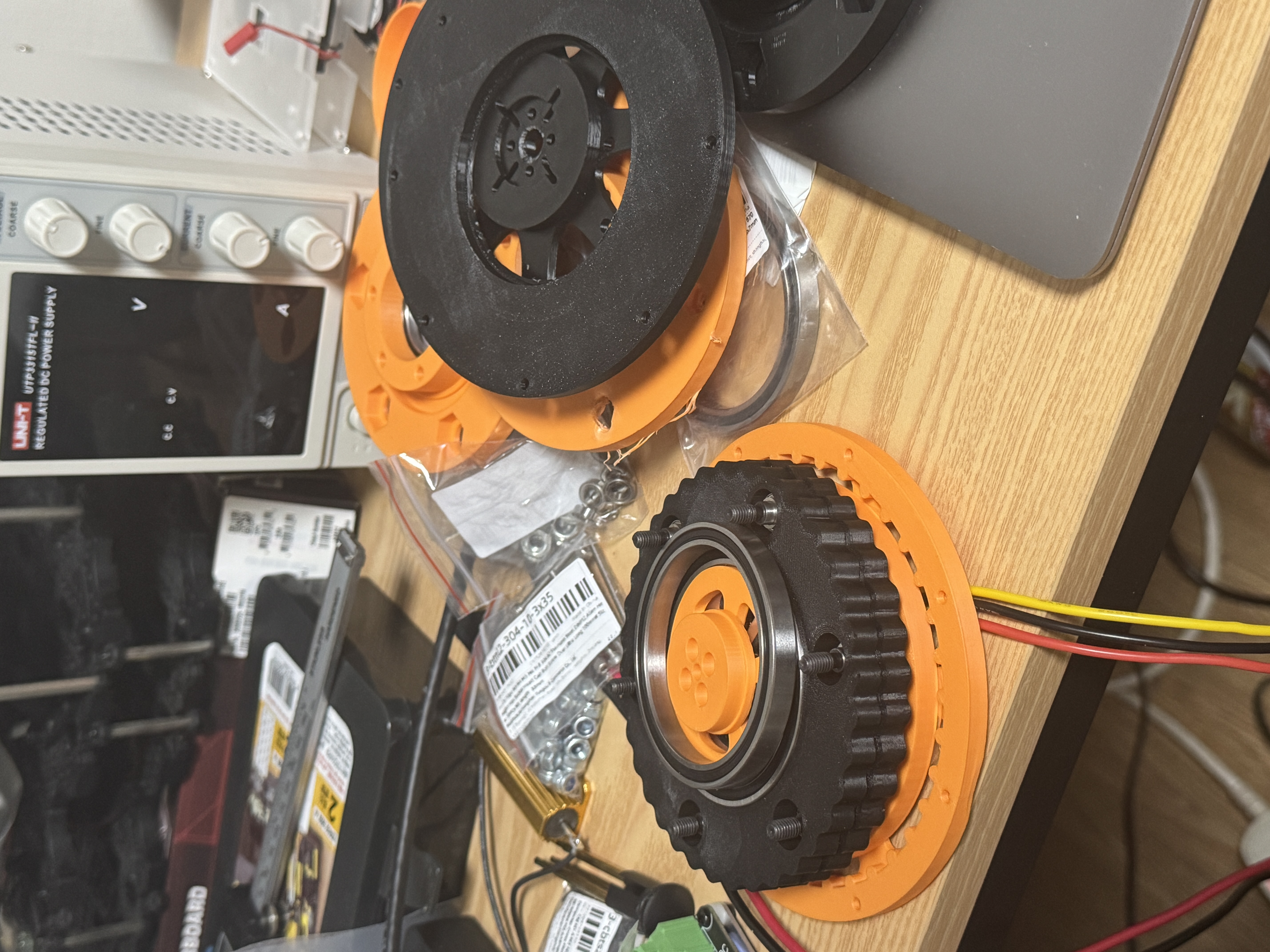
5. Problems Encountered
Eccentric Vibration
Because the motor was placed inside the eccentric shaft, the bearing responsible for transmitting the eccentric motion had to be significantly larger than expected.
The weight of the 6711 bearing produced noticeable eccentric vibration, which I considered severe enough to negatively affect the balance of a legged robot.
Clearance Between the Eccentric Shaft and Bearing
Even with carefully adjusted tolerances, the plastic components could not provide the rigidity of machined metal parts.
As a result, backlash between the eccentric shaft and the bearing reduced the responsiveness of the actuator.
Cogging in the BLDC Motor
Despite extensive motor parameter tuning, the motor was unable to hold certain rotor positions steadily. Instead, it occasionally snapped to a neighboring position due to cogging torque.
This produced a noticeable jerking sensation and affected the smoothness of the output shaft.
Limited Backdrivability
The 36:1 reduction ratio made the actuator difficult to backdrive whenever even a small amount of motor torque was applied.
The PETG housing also proved to be insufficiently rigid. During backdriving, the cycloidal disk occasionally slipped inside the ring instead of transmitting torque properly.
Difficulty Implementing Dual Encoders
One drawback of the cycloidal mechanism is that the center of the output shaft is hollow.
This makes it difficult to install an output encoder, complicating the implementation of a dual-encoder configuration that measures both motor position and output position.
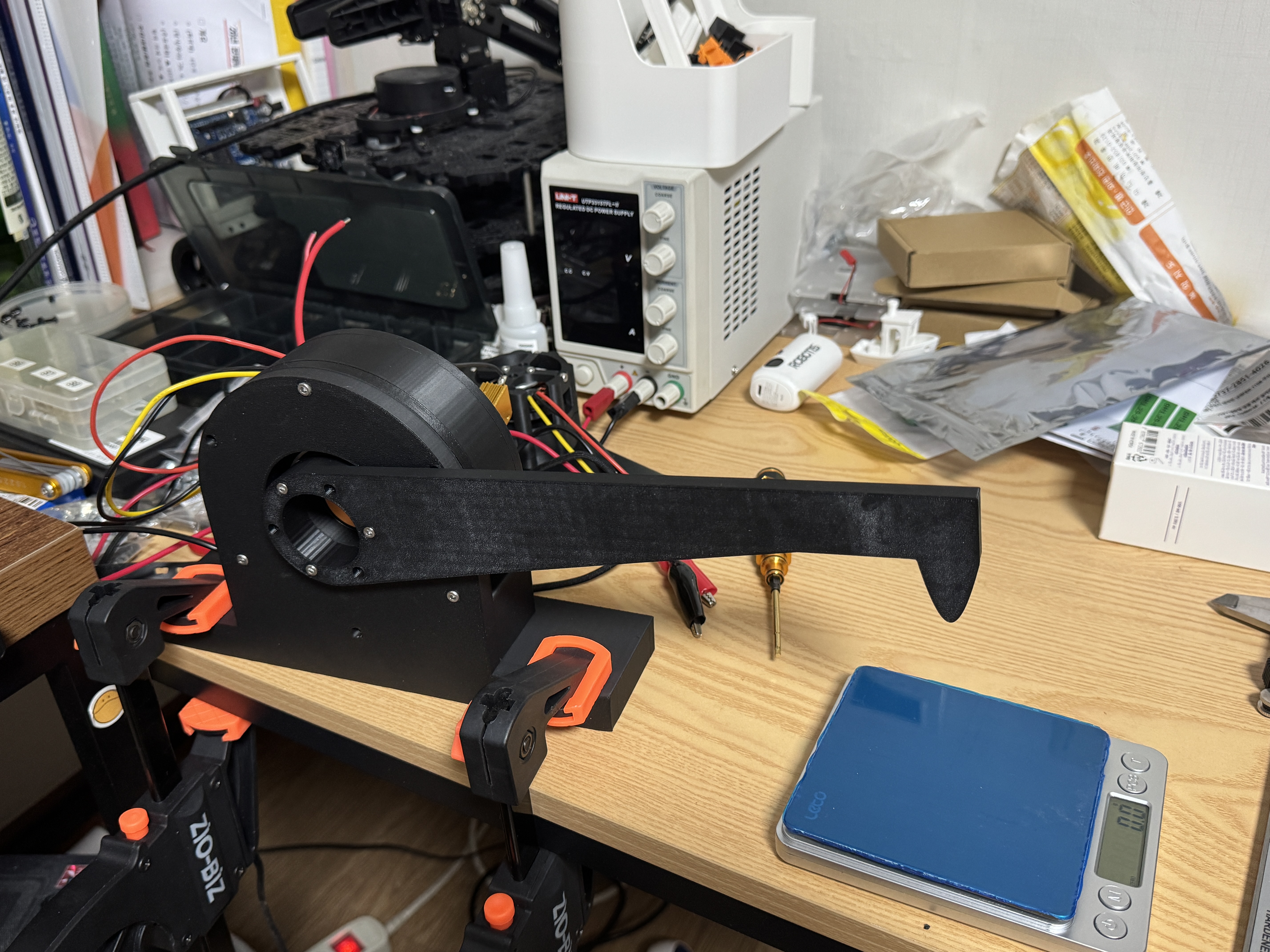
Conclusion
The final prototype achieved approximately 14 Nm of output torque while operating at 24 V and 10 A, demonstrating that a compact high-reduction actuator can be built using an inexpensive 5010 360KV BLDC motor.
However, the project also revealed several practical limitations, including eccentric vibration, cogging, poor backdrivability, and structural issues caused by the PETG housing.
Most importantly, I realized that if the goal is simply to build a capable robot, purchasing a commercially available actuator in the same price range is a far more practical an
d cost-effective choice than designing and manufacturing one from scratch.
